UPC custom software for six sigma design & manufacturing
UPC decided, around a decade ago, to deep dive into how six sigma methodology could be applied to high volume medical injection moulded products, typically with some added metal components to complete the device manufacturing package.
After some lack of progress, in the shower one morning there was sudden clarity of thought, which was hastily scribbled onto paper. We needed a unified design and manufacturing analytical method.
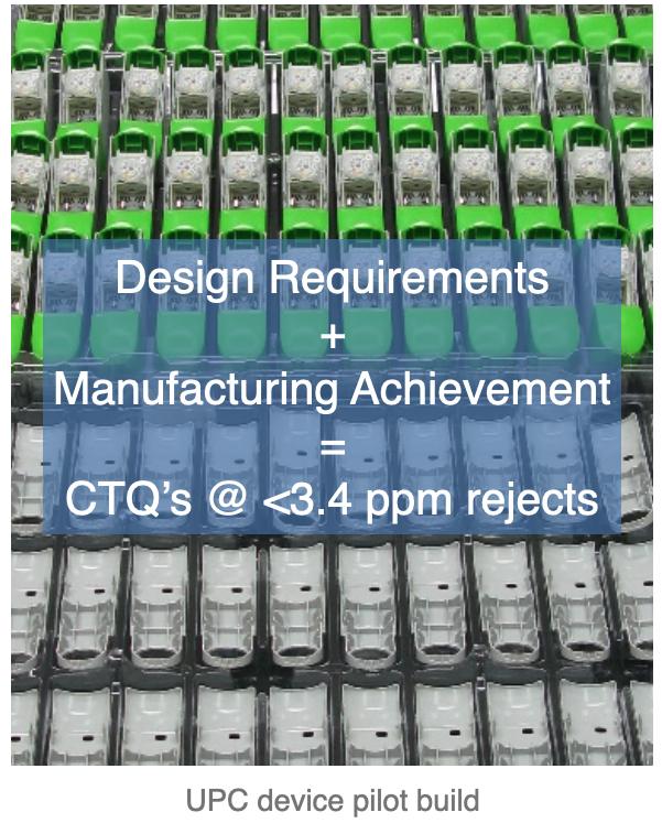
UPC firstly had to make sure that both the design (which assumes everything is at nominal and/or inside the tolerance limits) worked to less than a predicted 3.4 ppm defects ; secondly at tool validation and beyond that all component CTQ dimensions fell inside the CTQ performance limits based on standard deviations and averages of multiple measurements of the same manufactured dimension.
Note: This does not mean that all dimensions fall within tolerances to a Cpk of 1.33 or greater; as some dimensions prove not to be as significant as others in each stack or non-linear model. This was the key – to find out rigorously, what was a key dimension in the CTQ’s and especially which two part fits essential to function were in control or not in control in manufacture.
UPC custom software for six sigma design & manufacturing
UPC decided, around a decade ago, to deep dive into how six sigma methodology could be applied to high volume medical injection moulded products, typically with some added metal components to complete the device manufacturing package.
After some lack of progress, in the shower one morning there was sudden clarity of thought, which was hastily scribbled onto paper. We needed a unified design and manufacturing analytical method.
UPC firstly had to make sure that both the design (which assumes everything is at nominal and/or inside the tolerance limits) worked to less than a predicted 3.4 ppm defects ; secondly at tool validation and beyond that all component CTQ dimensions fell inside the CTQ performance limits based on standard deviations and averages of multiple measurements of the same manufactured dimension.
Note: This does not mean that all dimensions fall within tolerances to a Cpk of 1.33 or greater; as some dimensions prove not to be as significant as others in each stack or non-linear model. This was the key – to find out rigorously, what was a key dimension in the CTQ’s and especially which two part fits essential to function were in control or not in control in manufacture.
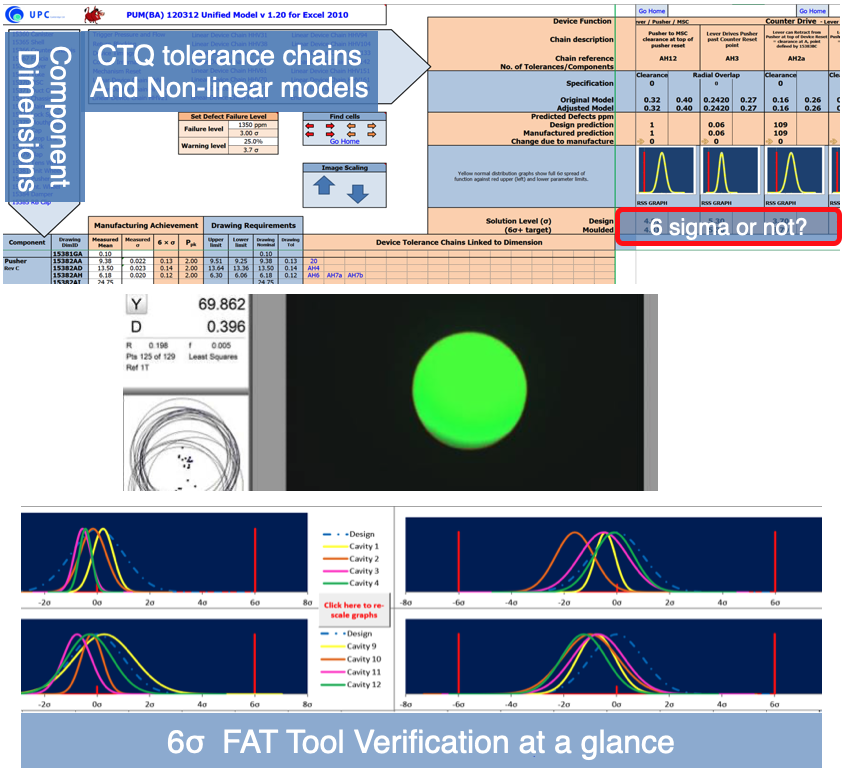
The Unified Model (β 2012) contained many macros, for ease of use
The aim of our system is to provide immediate graphic feedback for each device function across the top rows with common blocks for each function. In the end the yellow normal distribution lines showed the manufacturing result over the red chain dotted bell curve underneath – so if you can see red, the manufactured product is not to design intent. Further numerically the sigma level achieved can be seen, both for design and moulded performance.
On the left hand side the white columns are inputs for the measured mean (x_bar) and measured standard deviation (σ) from metrology data. Against the drawing dimensions this defines the Cpk (Ppk) for the dimension, and will light-up the linked outputs amber or red. Clicking on the chain(s), links to the design output for further inspection.
Below the unified model extract, is the associated Tool Verification package that shows graphically cavity by cavity achievement at a glance. This is real 16 cavity data from a 9 hour run with 4 lifts. Visually one can identify the two worst cavities very easily, which enabled better understanding across four companies working together in three languages.
The Unified Model (UM) and Tool Verification (TV) package enabled zero steel change on 16 cavity tooling through FOT,FAT,IQ,OQ± and PQ1-3.
The UPC Tool Verification system allowed metrology data to be converted to graphical output in less than a working day. By sharing on-screen data, only significant OOS dimensions were presented, then the Unified Model was used to define significance to function of the OOS in real-time. Yes/No decisions can be made rapidly with confidence; this is what avoided steel change in most cases.
Only one two part fit in a 21 component device caused issues, due to moulding warpage. After tool validation one hopes comes commercial success, but this can breed unexpected issues.
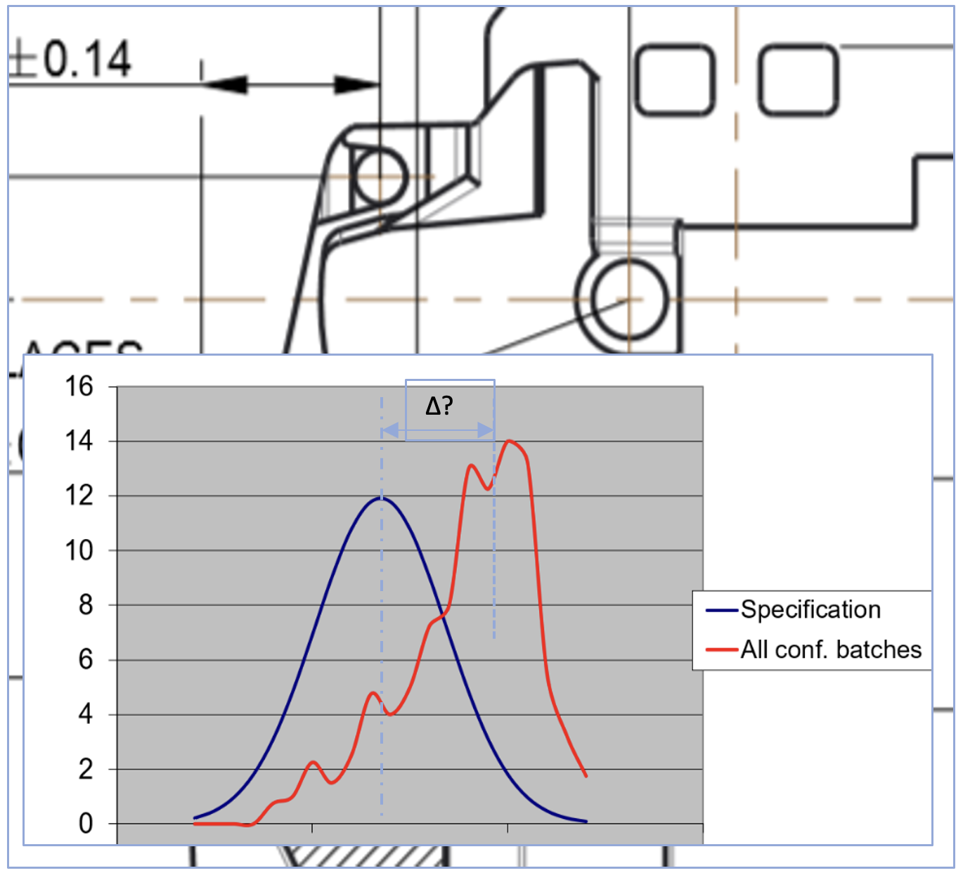
Opposite is a graph showing amalgamated test data for both Tool A and Tool B for a CTQ design output. The new tool was different to the older tool – which was correct? After a formal RTA using the UM we found the error was in the earlier tooling, that had not been noticed, due to the difficulty in making the measurement.
A great catch, speeding development
UPC Innovation